STEP UP 12VDC-B+ TUBE AMP PSU KIT
STEP UP 12VDC-B+ TUBE AMP PSU KIT
Hakkureiden käyttö putkivahvistimissa on edelleen harvinaista ja osittain ihan syystä. Toiminnallisesti hakkureissa ei ole mitään ongelmaa, kunhan ne on suunniteltu hyvin, käytetty laadukkaita komponentteja ja varmistettu mahdollisille huoltojen tekijöille mahdollisuus vaihtaa yksittäisiä komponentteja, sillä kokonaisia moduleja ei käytännössä koskaan ole saatavissa varaosana vuosien kuluttua. Valmiit kiinalaiset hakkurilevyt ovat toimineet vaihtelevasti: osa paremmin ja osa huonommin, mutta mikään ei vakuuttanut niin paljon, että olisimme halunneet käyttää niitä rakennussarjoissamme. Niinpä ryhdyimme suunnittelemaan oman simppelin step-up-konvertterin.

-
 STEP UP 12VDC in B+ out - hakkurivirtalähde rakennussarja putkivahvistimille30,00 € 24,19 €Hakkurivirtalähde, jolla voi nostaa 12VDC hehkujännitteen maksimissaan 300VDC B+ jännitteeksi. Taajuus ja takaisinkytkentäsäädöt mahdollistavat hyvän jännitteen säädön. Idea on käyttää 12VDC ulkoista virtalähdettä, joka viedään suoraan hehkuille (6,3V putket aina 2 hehku sarjassa) ja tälle hakkuri step-up virtalähteelle, joka tuottaa anodeille tarvittavan korkeajännitteen. LisätietojaTuotekoodi: 950-12V-B-PLUS-1
Ideana on syöttää hehkut suoraan ulkoisella muuntajalla 6V tai 12V:lla. 12V on parempi, koska se puolittaa virrantarpeen. Oikeampi olisi 12,6V, mutta 12V on riittävän lähellä, ja virtalähteitä on helppo löytää. 12VDC-syötöstä saamme hakkurille menevän jännitteen ja "hakkaamme" sen korkeataajuusoskillaattorin avulla putkille sopivalle tasolle, yleensä 200-400V:iin. Simppeli step-up -konvertteri toimii hyvin, kun virrantarve ei ole suuri (maksimissaan n. 100mA). Stereo EL34 -vahvistimessa päätimme käyttää kahta step-up-moduulia, jolloin virrantarve per moduuli puolittuu.
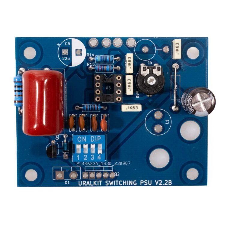
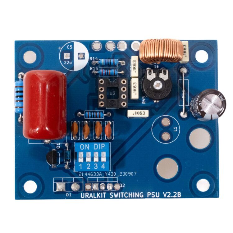
Kytkentään lisättiin 4x DIP-kytkin, joka vaihtaa oskillaattorin nopeuden määräävän konkan arvoa. Tällä kytkimellä saadaan oskillaattorin taajuutta säädettyä. Trimmeri säätää takaisinkytkentää ja siten rajoittaa maksimijännitettä. Trimmeri täysillä nousee ulostulojännite käynnistyksessä liian korkeaksi kytkennän suotokonkille (jos oletetaan, että ne ovat maksimissaan 500V:a), mutta säätämällä trimmeriä pienemmälle rajoitetaan maksimijännitettä, mikä korjaa tämän ongelman.
Jännitteen säätö tapahtuu sekä taajuutta muuttamalla (DIP-kytkin) että trimmeriä säätämällä. Kannattaa asentaa trimmeri hiukan puolen välin yli ja säätää sitten suunnilleen sopiva jännite DIP-kytkimien eri yhdistelmiä kokeilemalla. Trimmerillä saa jännitteen alas, mutta jossain vaiheessa häiriöt lisääntyvät, eli parasta on laskea jännitettä trimmerillä vain hitusen (mikä myös korjaa tuon käynnistyspiikkiongelman).
Kytkentään on valittu erittäin laadukas FET ja hakkurikela. Tämä on välttämätöntä, jotta lämpöhäviö säilyy kohtuullisena, eli hyötysuhde on hyvä. Osat on valittu sekä laskemalla että kokeilemalla. Haasteena on saada eri jännitteille ja virroille hyvin toimivat arvot.
Moduulin liitännät ovat siis DC in, maa ja DC out. Huomaa, että jos hakkuri nostaa 12V-jännitteen 300V:iin, jota kuormitetaan 100mA (300Vx0,1A=30W), vie kytkentä virtaa 12V:sta 2,5A (30W / 12V = 2,5A) + hukkateho. Käytännössä tällöin turvallinen voisi olla 12V 4A muuntaja. Pelivaraa kannattaa aina jättää. Stereo EL34 SE -vahvistimessa näitä hakkureita on siis 2 kpl. Hehkujen ja B+ viemä teho saadaan ruokittua 12V 7A virtalähteellä (84W).
Rakentaminen
Yleisohjeita rakennussarjojen kasaamisen tueksi
PDF muotoinen yleisohje pedaalirakentajille
Tarkista ensin toimituksen sisältö ja varmista, että kaikki osat ovat mukana. Komponentit voi olla hiukan eri näköisiä kuin ohjeen kuvissa. Tärkeä on, että arvot ovat oikeat.
Tässä laitteessa on yli 300VDC jännite, joten ole erityisen tarkka, että kaikki komponentit on oikeilla paikoilla ja oikein päin. Tee juotokset huolella ja tarkista jokainen juotos silmällä ennen siirtymistä seuraavaan.
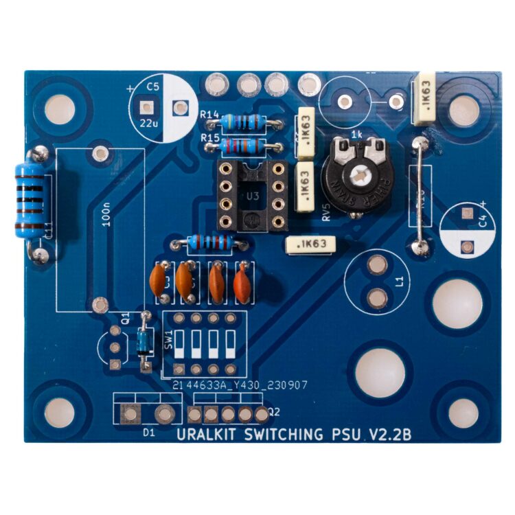
Asenna ensin matalammat komponentit kuvan, osalistan ja piirilevyn designaattorien (C1, C2, R1, R2...) mukaisesti. Ohjekuvassa R1 on eri kuin rakennussarjassa mukana toimitetta: katso aina oikeat arvot osalistasta, älä valokuvista.
Jatka asentamalla lisää komponentteja. Elektrolyyttikondensaattorissa pitää huomioida napaisuus eli asenna + ja - napa oikeisiin suuntiin. Myös transistori ja diodi pitää asentaa oikein päin eli niillä on asennussuunta.
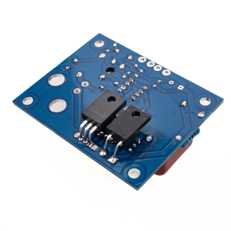
TO-220 koteloiset transistori ja diodi asennetaan kuvan mukaisesti. Voit toki asentaa ne toiselle puolelle, jos se on sovelluksen kannalta parempi, mutta varmista pinnijärjestys eli asennussuunta huolellisesti.
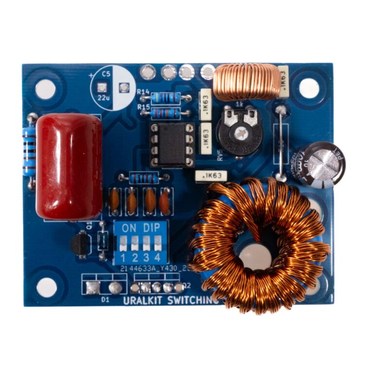
Viimeiseksi asennetaan hakkurikela. Se tulee ennen varsinaista käyttöön ottoa kiinnittää nippusiteellä tai liimalla piirilevyyn kiinni.
Tarkista ennen virtojen kytkemistä kaikkien osien oikeat asennuspaikat ja asennussuunta.
Testaus
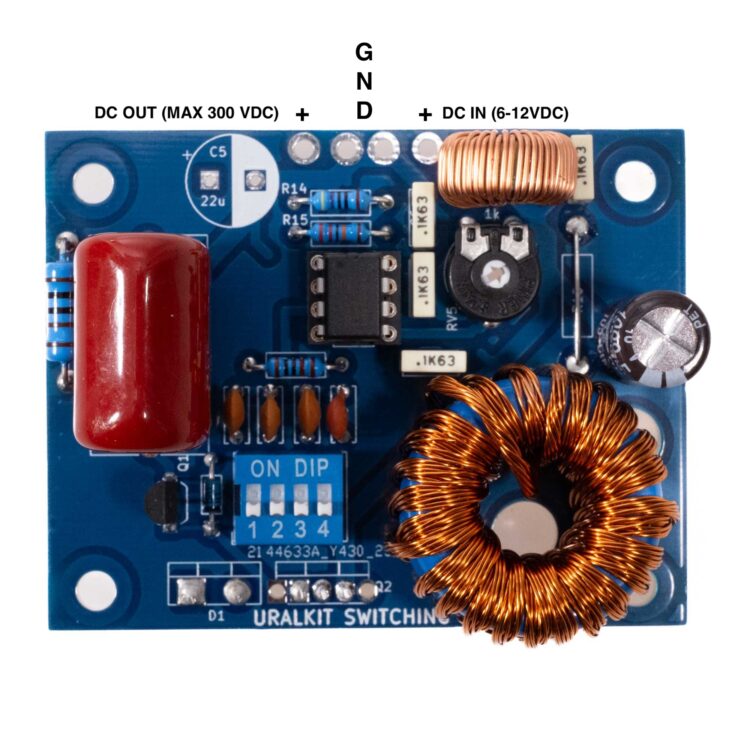
Säädä trimmeri puoleen väliin. Säädä 1, 2 ja 3 DIP ON asentoon ja 4 OFF asentoon. Jos sinulla on säädettävä jänitelähde kytke se DC IN - GND liittiimiin ja kytke yleismittari DC OUT - GND liittimiin. Kytke virrat päälle ja lue yleismittarista lukema. Pitäisi olla 200-400VDC. Säädä trimmeriä ja katsoa laskeeko jännite. Noin puolessa välissä trimmeri alkaa vaikuttamaan. Kokeile sen jälkeen dip kytkimen eri vaihtoehtoja ja säädä trimmeriä, jotta saat tuntuman miten taajuus ja trimmeri vaikuttaa jännitteeseen.
Jos kaikki ei toimi kuten pitää - ei hätää. Vika kyllä löytyy. Tutki osien sijoittelua ja juotoksia ja etsi virhe ja korjaa se. Jos kaikki toimii: Onneksi olkoon - olet rakentanut toimivan hakkuripowerin!
Käyttökohteet
Tämä tyypppinen Step Up hakkuri toimii parhaiten pienissä putkivahvistimissa: etuasteissa tai kenties single ended vahvistimessa. Miksei pienessä push-pull vahvistimessakin. Maksimi virta on noin 100mA, mutta tähän vaikuttaa ulostulojännite, ympäristön lämpötila, transistorin ja diodin jäähdytys, taajuus... Emme suosittele repimään näistä kaikkea irti. Jos tarvitset enemmän tehoa käytä toista sovellusta tai kahta levyä. Stereo vahvistimessa on kätevä käyttää molemmissa kanavissa omaa hakkuria. Näin saadaan vähemmän kuormaa per hakkuri ja myös erotettua kanavat toisistaan.
Pienillä virroilla puhdasta jännitettä saadaan enemmän eli jännite nousee kyllä yli 400V:n. Tosin etuasteissa harvoin tarvitaan näin korkeita jännitteitä.
Hakkurin ulostulo on hyvin puhdas. All Octal SE amp häiritaso on niin pieni, ettei sitä kuule korvalla lainkaan.
Kytkennässä ei ole kuin 1uF suotokonkka valmiina eli tämän piirin jälkeen lisätään usein 10-100uF suotokonkka päätemuuntajalle menevään B+ linjaan. Hakkurin jälkeen ensimmäisenä suotokonkkana on suositeltava käyttää hyvin laadukkaita elektrolyyttejä.