UralTone TV-Reverb - Build Guide
UralTone TV-Reverb - Build Guide
The UralTone TV reverb is Teemu Viinikainen's interpretation of a perfect single channel Deluxe Reverb.
The TV Reverb circuit is a Deluxe Reverb's second channel without tremolo and it uses a Princeton Reverb chassis / cabinet. It has 22W of output power and all transformers are the same as in the Deluxe Reverb. A choke is also used with the circuit, as in the original. As an additional control, the TV Reverb has a Tweed-potentiometer which blends in the 50's style mid-range emphasized sound. When the tweed is set to zero, it won't affect the tone. The second mod is a middle potentiometer which is an excellent addition to the stock tone stack and works similarly on the Super Reverb. The Dwell potentiometer controls the reverb, and it can be used for fine-tuning the length and nature of the attack.
In this article, the different stages of assembly are shown. Note that some of the details aren't reviewed and purpose of this guide is more to familiarise the process in general. However most of the details are covered.
When building, always follow the layout picture and parts list supplied with the kit. It's always up to date version and connected to parts kit supplied. Availability of the components etc. may cause changes. Over time there will always be improvements or changes as well. The layout picture and the parts list included with the kit are always the correct ones to follow and the most recent version.
Use the layout and BOM as book keeping help while assembling the amplifier. Mark all components used / installed to BOM and layout picture. This helps you to be sure all of the solder joints and wirings are done and track possible errors or so.
-
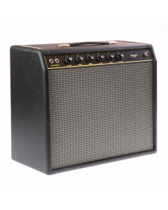 UralTone TV Reverb amplifier kit - Teemu Viinikainen Custom Deluxe Reverb
From €765.00 €616.94
To €1,662.00 €1,340.32
The perfect single-channel Deluxe Reverb (22W) kit in a Princeton Reverb chassis.
Learn MoreSKU: 950-UT-TVREV
Instructions for measuring and startup

First, always check that all parts are included in the delivery. If you find any deficiencies, please get in touch with us by e-mail or via the "contact us" form on the pages. Please note that the components may look slightly different from the photos. Also, note that the voltages of the parts may be higher than what is written in the list. We try to keep the models of the components the same, but sometimes we have to change the manufacturer or model of a part due to poor availability. So, if a part is a slightly different color, don't panic; each component has the necessary values marked on the side of the component. Read the notes on the part list carefully.
Building the amplifier involves three stages. Installation of the parts to be attached to the chassis and their incomplete wiring, laying of components and soldering of the PCB board, and installation of the PCB to the chassis and its wiring. You can do the first two in the order that suits you. However, we recommend that you follow the order of the images below.

Start by fitting all components and parts which are attached to chassis. Mount the small parts first, this makes the work bit more easy when the heavy transformers are fitted last.

Fasten the small parts of bottom face of the chassis:
- 6x spacers with M3x6 screws and star washers. (Some kits may use M3X5 without washers.)
- 3x rubber grommets
- 4x Noval-sockets (preamp tubes) - Note the orientation, space between pin 1 / pin 9 points towards two'o clock. Fastening by M3x6 screws.
- 3x Octal-socket (output and rectifier tube) - Note orientation, the guide pin with slot on center of the socket (between pin 1 ja pin 8) points towards four'o clock. Guide the ground wire in the solder lug 8. (See picture below:) Fastening by M3x6 screws.

Cathode - ground wires guided in the solder lugs.
Note: The TV reverb is built on a Princeton chassis. The mains transformer of the circuit is a larger in size and the inner mounting holes of the transformer are cut open on chassis. If the corners have not already been cut off, cut off the small corner pieces of the mains transformer opening.)

Fasten the parts to back panel. The panel is attached by the parts.

Rear panel parts:
- 1x Potentiometer.
- 3x RCA-connector. Use star washer between the connector and chassis.
- 2x Jack. Use star washer between the connector and chassis.
- Mains switch - Use star washer and nut between the switch and chassis.
- 2x Fuse holder

Swich mounting in detail - use star washer and nut between the switch and chassis.

Fasten the front panel parts. As well as on rear, panel is attached with the components.

Mount:
- 6x potentiometers. There's no star washers between the potentiometers, except the TWEED potentiometer, which is supplied with one (second potentiometer from left). Note: Alpha potentiometers are fitted with the guide pin for locking the potentiometers in right position. This pin is bit too tall, so cut approximately half of the length of it. Make sure the guide is flush with the front panel. Pin is made out of cast aluminum so it breaks easily.
- Pilot light. This is bit tricky and tight with the space to assembe. If the pilot light is supplied with the large star washer, fit this one between the chassis and body of the light. This way tightening the nut is easier. Try to secure the nut well: if the nut is loose and the jewel is tightened too much, replacing the bulb will be easier. With loose nut, the jewel won't come off and the nut opens instead. This then requires opening the amplifier. Keeping the nut tight and jewel loose, switching bulb can be then done without of opening the amplifier.
- Leave the jacks uninstalled for now
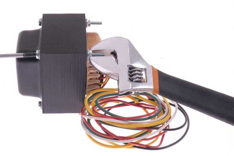
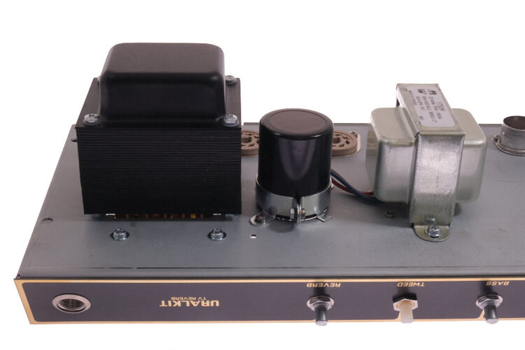
When light parts are done, continue with the transformers. First check the mains transformer screws for proper tightness. The tolerances over here are quite large, so you may need to reopen the screws to make the transformer to go through the chassis. If needed, reopen the trouble corner and reposition the screw. Note: mains transformer is fastened by separate M4 nuts and large washers. (check the picture below)

Attach the reverb and output transformers to chassis and guide the wires through the rubber grommets. These transformers are secured with M4 screws and nuts.

Mains transformer seen on outside: the nuts holding the core and end bells are on outside of the chassis.

Project should look like this by now. The choke is mounted inside the chassis.
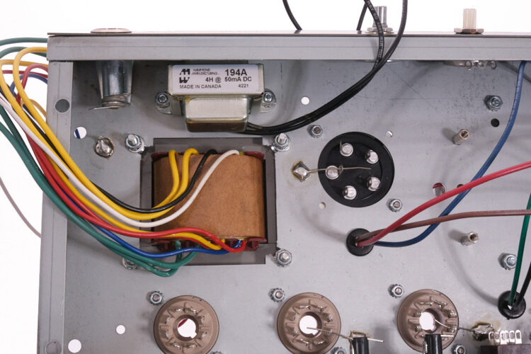
Fix the mounting band of the can capacitor with two M3X6 screws. Leave these loose for now for some free movement. Press the can capacitor in the holder, see the orientation of it. Guide the ground wire in the common negative solder lug.
Note the mains transformer mounting from bottom side: Use washers under the nuts.
Mount the screw holding the can first. You can bend the lips bit inward, if the screw is too short. When the band is tightened, tighten the screws on chassis side. This order of assembly prevents crushing in the capacitor sidewall.

Prepare the mains wire: Peel off the outer insulator within the distance of 25-30cm, as so the blue wire can be soldered to mains switch. Do the estimation with help of the chassis. Be generous, removing clipped in strain relief without the proper tools is difficult. Over here few extra centimeters is good investment, excess wire can be clipped off later on.
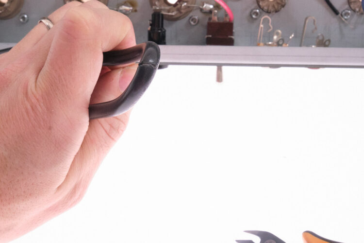
Cutting the mains wire is exact work. Don't cut the insulator of inner wires. By bending the wire in tight angle and cutting carefully the outer insulator usually tears open without of getting too deep. Going round the wire the insulator is then finally cut. If you cut the inner wire insulators and expose the copper, cut the wires and shorten the wire another 30cm. Do not use wire with damaged shielding.
The strain relief need a tool for fitting but can be done with common tools: link to guide

The project is progressed for starting soldering. On following, the wires from the transformers and mains wire is soldered to chassis mount parts.
Start with the reverb transformer. Leave the red wire unsoldered.
The wiring of the kit resembles the same style used on old vintage Fenders. The lenght of wire is "right", not too short as direct line between two points nor too long to fill up the chassis by rat nest of wiring. Use the curvature of wire for nice curvy wiring all over.

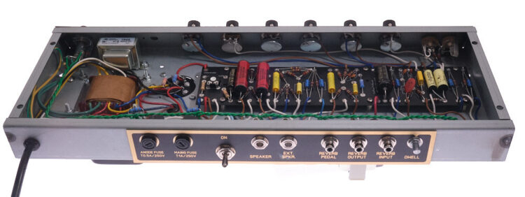
Solder the speaker output wires of the output transformer. The layout picture doesn't have the black wire between the jacks, but you may solder this. This ensures the ground connection if the nut of the jack gets loose. Note the jumper on switching jack on left. The wiring is done by using the excess wires cut from transformer wiring. This reusing of wires keeps the colors and gauges of the wires uniform. The solder lug of green wire of external speaker can be left unsoldered now. There's another wire to be soldered here later.

The blue and brown wires are soldered to output tube sockets. Solder as well as the ground wire.
The blue wire of the mains cable is soldered to mains switch and brown one to solder lug on side of the fuse holder. Use shrink sleeve on the lugs of the mains switch.
Note: the wiring of the fuses are routed towards the back. The fuse holders are covered with shrink sleeve and this routing enables covering the fuse holders without of removing the wires. (this is done later, not now)

Solder the wires coming out from the mains transfomrer:
- Red (thin wire) pair to rectifier tube socket pins 4 and 6.
- Yellow (thick wire) pair to rectifier tube pins 2 and 8. Use the excess wire from previous step to continue the wire to fuse holder side pin. Solder the rest of this wire to top connection of the fuse holder. End of this wire is connected to can capacitor. Don't solder the capacitor lugs yet.
- Yellow (thin wire) to common negative pin of can capacitor.
- Blue (thin wire) is left as is for now. It's later soldered to circuit board.
- Green (thick wire) to pilot light solder lugs. Use inner pair of holes, make sure there's no solder bridges to shorting to light body.
- Black and white (mains in) wires to mains switch to center pair of the solder lugs. Insulate the soldering joints with shrink sleeve.

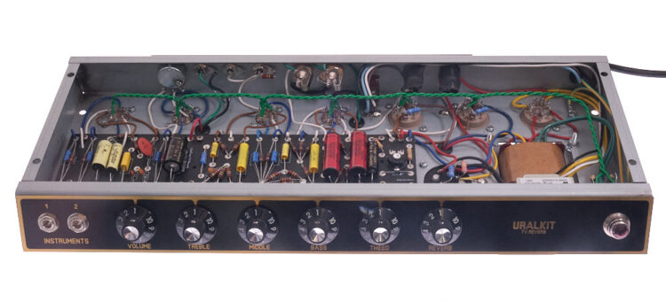
Project should look like this by now.

Solder the output tube socket grid stopper and screen resistors, the 220k bleeder resistor of can capacitor and the return line resistor of 220k on RCA connector.

Solder the jumpers back of the potentiometers. Alpha potentiometers have usually some grease on the back cover and this needs to be removed first. Use isopropanol, alcohol etc. and wipe the backs of the potentiometers. After this sand of file a small area where to solder.

Input jacks are easy to prepare outside of the chassis, using the chassis as bench. Fasten the jacks as in layout and solder the resistors. (Note: If the solder you use has plenty of flux and spits this all over, cover the panel before soldering.)

Mount the pack of jacks. Use star washers between the jacks and the chassis.
Chassis preparations are now done and this can be set aside now for a while.

It's possible to assemble the circuit board per type of component or low components first order. The later is better, because the parts are pressed against the board when it's turned aroud for soldering. On following pictures, this technique is used.
To keep on track the build, mark the parts used to printed BOM.
Some of the pads are shared, so solder only those which ones aren't populated later on with another component or wire.

Cut the wires of the components installed, both soldered or non soldered. Make sure the wire is short enough, cut in the area of pad.

Populate more components, bit higher ones than previously.

Until all components are on board.
Note: The board above is populated with optional Jupiter capacitors. The installation direction of these is marked on the housing with a line and the installation direction is marked as well on layout and show the picture. The orientation is not critical. The supplied Mallory capacitors can be installed either way.

The same as previously on alternative view.
You may solder the wires according given lengths on the layout picture or solder the wires when the board is attached to chassis.

Fasten the board to the chassis by six M3X6 screws. Guide the four ground wires in the eyelets on top edge of the board. Solder the red from reverb transformer and blue wire from mains transformer to board.

Solder the red wires between the can capacitor and the circuit board. Solder a 10k resistor on the can capacitor.
Solder as well the black wire from negaitive terminal and the circuit board / bias circuit. This wire is missing on the picture.

Solder cathode (blue) wires on back panel side from the board to tube sockets and connectors.
Follow the given lengths of the wires. Route the wires parallel to chassis for protection of interference. Don't run the wires parallel, specially don't mix the white gate wires with brown anode wires. If wires are crossing, aim for right angle crossing for minimum crosstalk. Mark all wires soldered to layout picture. Note the V2 socket of two wires across the socket.

Continue with gate / signal wiring (white). Note the two missing wires of dwell potentiometer and feedback from speaker jack.

Solder the anode (brown) wires. These are running 5 - 10mm above the cathode and gate wires.

Solder the wires on from panel side. Note the VOL-TREBLE-MID-BASS-TWEED potentiometer wiring in between. These are run on corner of the chassis and aren't visible in the picture above.
The Alpha potentiometers have grease layer and this makes soldering difficult. In order to successfully soldering clean the backs of the potentiometers with degreaser, such as isopropanol or similar. Then sand of file the area where the solder is applied. Use the cut legs of the components or piece of single core wire as jumper.

Finally solder the heater wiring which is routed above the tube sockets.
Cut the green heater wire in two equal pieces. Solder the ends of the wires to lugs 4-5 and 9 of V1 and twist the cable in pair until it reaches the socket of V2.

Solder a new wire and the wire from the V1 to pin 9 of V2. Solder the wire from V1 to pin 5 of V4. Solder the new wire to pin 4 of V2 and continue the wire to pin 5 forming a bridge between.
Twist the new pair until reaching socket V3 and so on.

Use the large shrink sleeve on the fuse holders as on picture.

Solder the 100ohm heater balance resistors on the lug on chassis and guide the other ends to pilot light lugs. Solder the resistors and heater wire ends.

Heater wiring is ready.
Attach the potentiometer knobs, insert the pilot light and screw in the jewel. Do not over tighten the jewel. Install the fuses on the holders with given specs.
The amplifier installation work is complete. Next, following the layout image, check that all the wiring has done right and that the parts have been laid out correctly. Go through the circuit wire by wire, part by part, and mark the checked part on the layout picture.
The check list for powering up and measurement points values is found here:
https://docs.google.com/spreadsheets/d/1CRP6kfBlP8VWHthzhgFmR605qaoRH0X6vjR967P3Yy4/edit?usp=sharing
Follow the instructions of the opening page and look the measuring instructions of the tab of the TV Reverb on bottom left corner. Turn all potentiometers and bias trimmer to zero. (Bias zero is the most negative voltage.)
When everything is correct, measure with a multimeter as well as the integrity of the grounding and rule out short circuits in the power source:
- Measure using the resistance range of the multimeter: One probe to any part of the chassis frame and the other to the negative lug of the capacitors C1, C6, C11, C15, C16 and the common negative terminal of can capacitor, the grounds of the potentiometers / black wires and the bodies of the jacks. The results should read zero ohms.
- Measure in the resistance range of the multimeter: one at a time, measure the resistance over the positive poles of the can capacitor and the chassis. In this measurement, the resistance is small at first, but settles to several hundred kilo-ohms. Make sure to wait for the meter to settle. A small resistance, zero or only a few kilo-ohms can be a sign of a possible short circuit, which should be looked for before connecting power.
When the measurements and checks have been done successfully, you can connect the power to the device. First, install the fuses and the rectifier tube in place, the other tubes are left uninstalled. Measure the voltage from the ground and positive poles of the multi-tap capacitor and the capacitors of the PCB. The unloaded voltage is approximately the same at all positive poles and at this stage well above the results of the measurement points marked in the layout image. If at this point there is no voltage on the capacitors, the device smokes, sparks, or does something unexpected, turn off the power.
Before troubleshooting, make sure by measuring that the capacitors of the power source are de-energized and the device is disconnected from the mains. The layout picture also shows the AC voltage measuring points. If necessary, these can be measured in the 1000Vac range of the multimeter if there are problems with the device. Of these, those marked with one arrow are measured relative to the ground, and those marked with two arrows are measured between the arrows.
Install the rest of the tubes and connect a speaker or an dummy load to the output. Turn the knobs to zero. Turn on the power. Let the amplifier settle down for a few moments and measure the voltages at the measuring points. At the same time, make sure that the amplifier does not do anything unexpected.
Measuring points 400V, 325V, etc. are marked in the layout picture / voltage map. The values of these measuring points are measured relative to the ground, i.e., the black measuring head of the multimeter is attached to the body of the device, and the measurements are made with the red one. It is advisable to even sit on your other hand while you make the measurements. Use the 1000Vdc setting as the measurement range and allow approx. 10% deviation from the given measurement results.
The voltages at the measuring points are always affected by the dispersion of the tube parameters and the differences in current consumption. Another factor that changes the results is the magnitude of the mains voltage. This can vary between 220-240Vac, which is easily seen in the measurements. It is better to check the voltages more as a whole and allow them to slide in one direction or another. Large deviations in a single measuring point when the others are in place can reveal, for example, the wrong size of resistor on the PCB. You should also rely on your ears: If the amp sounds bad, something is wrong.
Note: If you measure voltages without tubes, the voltages with the mains transformer unloaded are always higher. Except for alternating current measurements of the mains transformer, always measure the voltages with the tubes.
When the measurements are done to an acceptable level, the amplifier is ready to be fitted in the cabinet. The details of this is not covered here, but here's some things to consider:
- TV Reverb kit is supplied with the parts for Fender style reverb tank wiring. Instructions of the assembly is found here: Fender -style reverb tank wire build guide
- Speaker cable is as well in for of the kit and resembles by the looks of the ones used in Black Face amplifiers.
- Rever tank needs to be enclosed to bag intended for the purpose. This prevents the feedback in cabinet. The bag an be bought as ready or do it out of same tolex as used covering the cabinets.

Edit: 31/5/2022 - The hum of the reverb
Some of the people who built the series have found the hum of the reverb to be bit too loud. The original Fender circuits have used the body of the device as grounding and the kit has been implemented in the vintage spirit accordingly. The amount of hum can be reduced by isolating the RCA connectors of the reverb return and the footswitch from the chassis. The change moves the ground path of the reverb signal directly to its amplification stage, so the currents passing through the chassis do not add up to the signal.
For modification, you need an 11mm - 12mm drill, a piece of 0.5mm black PVC wire and two sets of Switchcraft 1028/29 insulating plates. The parts are not included in the kit's component delivery.
Disconnect the RCA connectors of the reverb footswitch and the return and move them aside so that you can drill the hole in the case and the panel. If you make a change to the assembled amplifier, leave the panel in place so that the through-copper can also be drilled open, or if you make changes during construction, remember to drill the holes in the panel larger as well. The panel does not act as insulation without drilling. Carefully drill the holes so that the drill does not hit the components or wires inside the device. If necessary, make room by moving parts aside. After the holes are made, carefully clean all the metal shavings from the chassis.
Insert the RCA plugs with the solder lug and the collared black insulating plate nd fasten the RCA connectors back into place. The brown insulation board is not needed on the panel side, but if it fits under the nut and washer, the part is fine. Check infinite resistance between the RCA connectors and the chassis by measuring the resistance / conductivity of the multimeter.
Solder a piece of wire between the ground lugs of the RCA connectors. From the second connector, a wire is soldered to the connection board to the GND point for the negative pole of capacitors C1 and C16. The return of the echo signal now takes place through its own grounding. If you want, you can also try the same change in the Princeton and Deluxe Reverb building sets.