UralTone Micro ECL84 mini amp - Build Guide
UralTone Micro ECL84 mini amplifier build guide
The UralTone ECL84 is the louder, angrier model of the Micro Amp series. The ECL86 is at its best with warm cleans and very little distortion. The ECL84 Micro Amp, on the other hand, shines with the biggest, even fuzz-type distortion levels. The amplifier actually requires that it be beaten and teased a little. The sound is solid, tight, and well put together. The harmonic richness increases as the distortion increases. This is not aimed at Toto or Gary Moore cover bands, but a mini-amp ideally suited for tight, gritty (fuzz) rock or heavy riffing or jamming sessions.
Of course, the UralTone ECL84 also produces clean sounds and, if necessary, jazz or blues sounds.
The design of the UralTone ECL84 amplifier started from the desire to use tubes, which are lying around in warehouses around the world, but for which no one has really found a use for. After many tests, the ECL84 triode-pentode and the E92CC double triode were selected. The ECL84 was originally a television tube, and the E92CC is a workhorse found inside ancient computers. These are no traditional amplifier tubes, so you have to explore their use from a slightly new perspective. Since these tubes are not designed to work as linearly as possible in audio circuits, it is not worth using them as such. For HIFI devices, it is generally advisable to choose tubes designed to amplify the signal as linearly and distortion-free as possible. This is rarely the goal in guitar amplifiers, so many exciting tones and distortion spectra can be obtained using the more exotic tube types.
The world's warehouses are full of both types of tubes without any rational use, so availability should be good well into the future. And these tubes have very long service lives.
-
 UralTone micro amp - ECL84 - Guitar Tube Amp Kit€169.00 €136.29UralTone ECL84 micro amp is a full tube amp powered from external 6VAC PSU. Learn MoreSKU: 950-MICROECL84
UralTone Micro ECL84 kit - BOM - Kit parts list
UralTone Micro ECL84 Kit - Wiring Diagram
First, always check that all parts are included in the kit. If you find any deficiencies, please get in touch with us by e-mail or via the "contact us" form on our website. Please note that the components may look slightly different from the photos. Also, note that the voltage rating of the parts may be higher than what is written in the list. We try to keep the models of the components the same, so we sometimes have to change the manufacturer or model of a part due to poor availability. So, if a part is a slightly different color, don't panic; each component has the necessary values marked on the side of the part. Read the notes on the part list carefully.
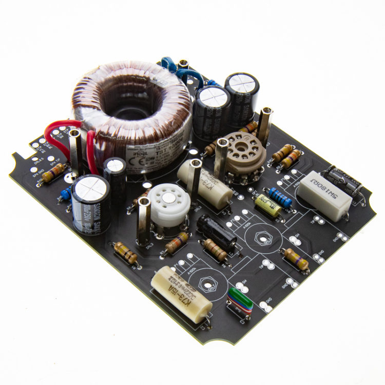
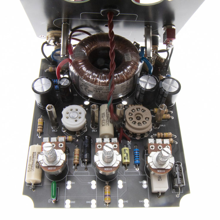
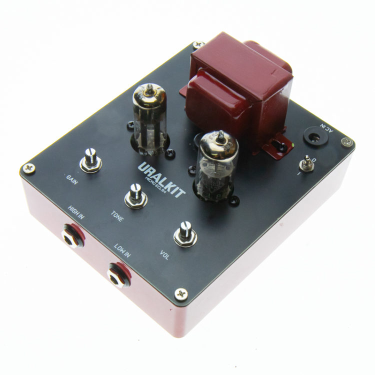
The amplifier is built between two PCBs. The lower PCB has the actual circuit of the amplifier and the mains transformer; the output transformer, speaker output connectors and power switch are attached to the cover plate. The construction of the amp is closer to an effects pedal; the scale is just a little bigger. In this series of pictures, we proceed one sub-assembly at a time. We recommend that you familiarize yourself with the build instructions before assembling. This way, you will have a clear idea of how it should be done.

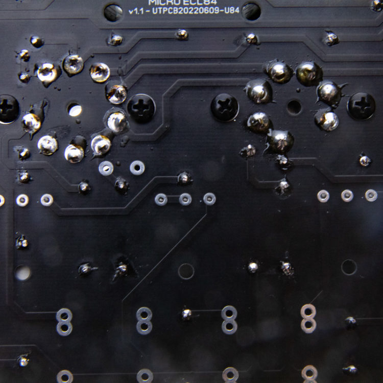
Micro ECL84 PCB. The numbering and values of the parts are printed on the plate. (If the value printed on the PCB differs from the parts list value, the parts list value is correct.)
The amplifier can be built either with the top panel that comes with the kit or by drilling the enclosure, as some of the Micro series amplifier prototypes are built. In this case, the cover plate PCB can be used as a drilling template. Ready-made holes have been made on the top panel accordingly. These are marked with DRL and bore diameter.
In this guide, the amplifier is made more easily without drilling by using the cover plate
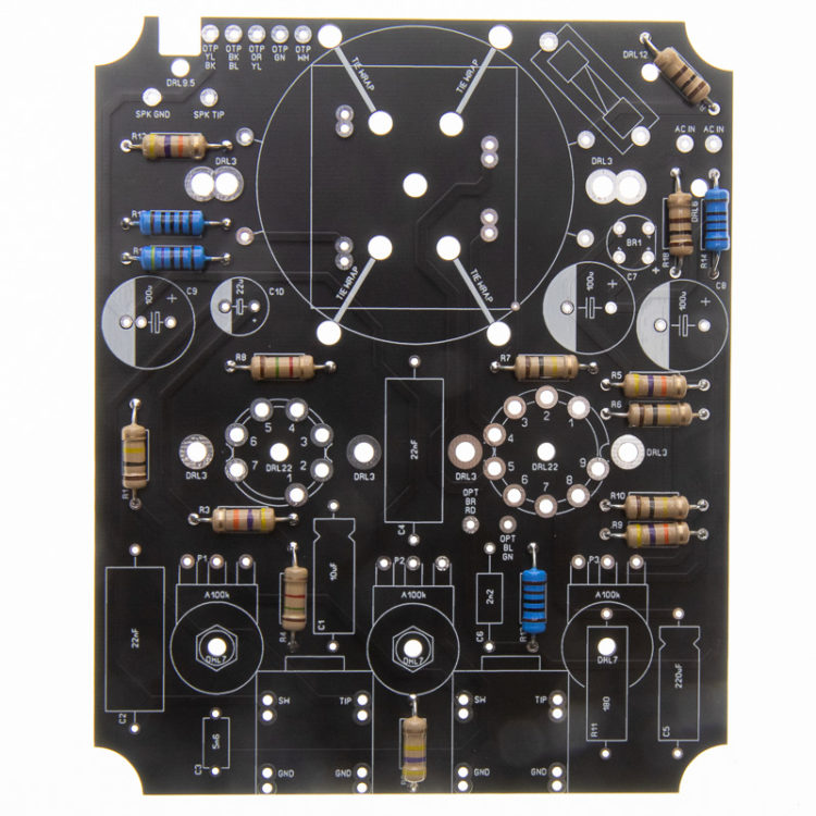
First, install the carbon film resistors on the board. On the resistors, the value of the parts is marked with colored rings. You can either google color value tables or use a multimeter to find the correct value. The mounting direction of the resistors does not matter. Still, for a more elegant build, it is advisable to use a set mounting direction, which makes it easier to read the value of a part later if the device is repaired, for example. In the pictures, the parts are laid out parallel to the screen printing (in the same orientation as one would read).
The parts soldered on the bottom side of the PCB should always be soldered using the lowest-in-height-first technique. In this way, the parts stay neatly on the PCB's surface without having to press them into place separately. The same practice also makes soldering easier because you don't have to turn the legs to a 90° angle.
Install the metal film resistors on the board. In the circuit, the larger metal film resistors of higher power ratings are used in the power source. Note: Do not mix up the 100ohm carbon film and metal film resistors.

Install the 5W power resistor on the board
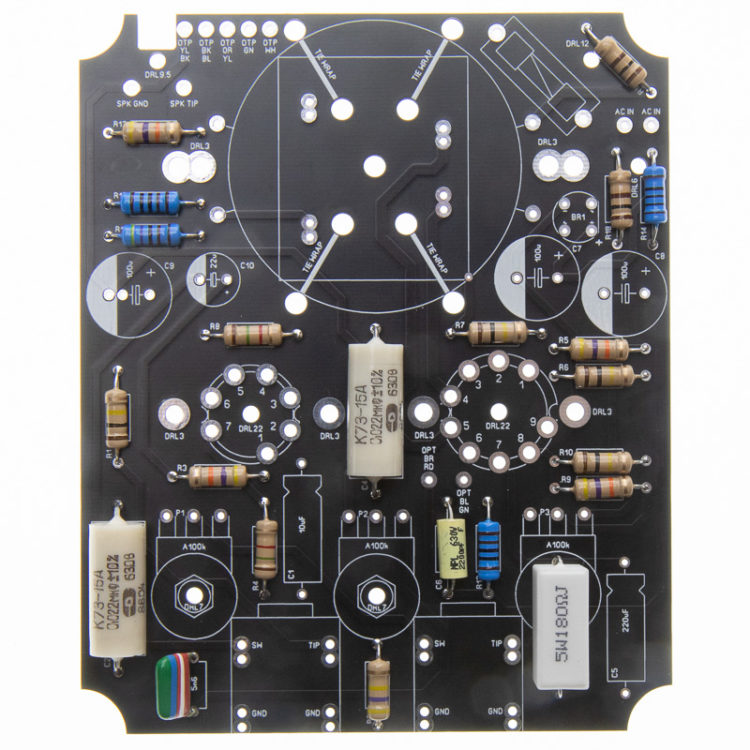
Install the plastic film capacitors on the PCB. These do not have a fixed mounting direction and can be installed either way.

Install the electrolytic capacitors on the PCB. These have a specified polarity and must be installed in the correct orientation. In capacitors installed horizontally/axially (wires at the ends), the positive pole is marked with a groove made in the housing. Align the screen print on the PCB and the grooved end of the capacitor housing. Vertically/radially installed electrolytic capacitors have the negative pole marked with a white/grey stripe. On the PCB, the negative is marked with a white filler on the components printing.
Note: The vertical electrolytics are easier to install after installing the tube sockets.

Install the rectifier bridge. This part also has a specific mounting direction. The positive pole is marked on the top of the component with a + symbol, the PCB is also marked with the same, and it has a longer connecting wire.

Continue the build by installing the tube sockets on the PCB. Sometimes the legs of the tube sockets are bent slightly at an angle, so we recommend checking that the tube socket is parallel to the PCB. Solder the socket first on one side and bend it in the appropriate direction. When the base is straight, solder all the pins. Attach and solder the fuse holder at the same time.
If you didn't install the vertical electrolytic capacitors before, install them now.

Attach the six distance bolts to the PCB. An m3 star washer is installed between the socket and the PCB as an additional riser. Attach the rubber amplifier foot with the M4 screw and nut, as shown in the picture.
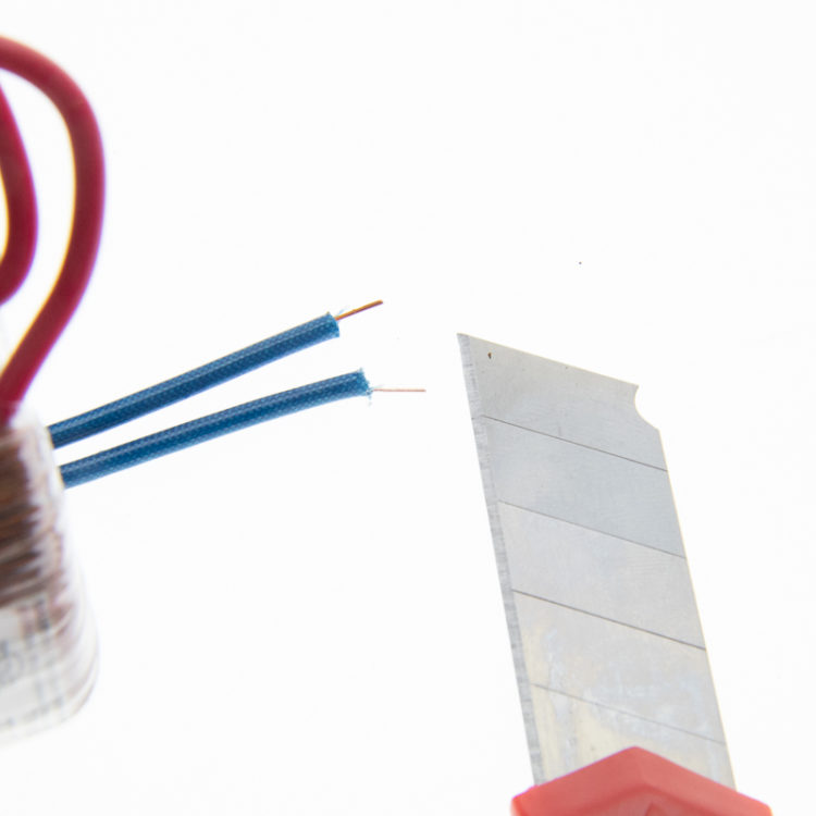
Cut the wires of the small mains transformer supplied with the kit to short lengths. They should measure approximately the height of the transformer plus 5-10mm. The 6V coil leads are the same copper wire as the transformer coil and this is varnished to prevent short circuits. To be able to solder to the PCB, the varnish must be scraped, sanded or burned off. When the varnish has been scraped off, etc., pre-tin the ends of the cables. If the solder does not stick, clean the wires more.

Push the transformer into the rubber foot and thread the wires into their pads on the PCB as shown.
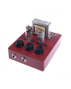
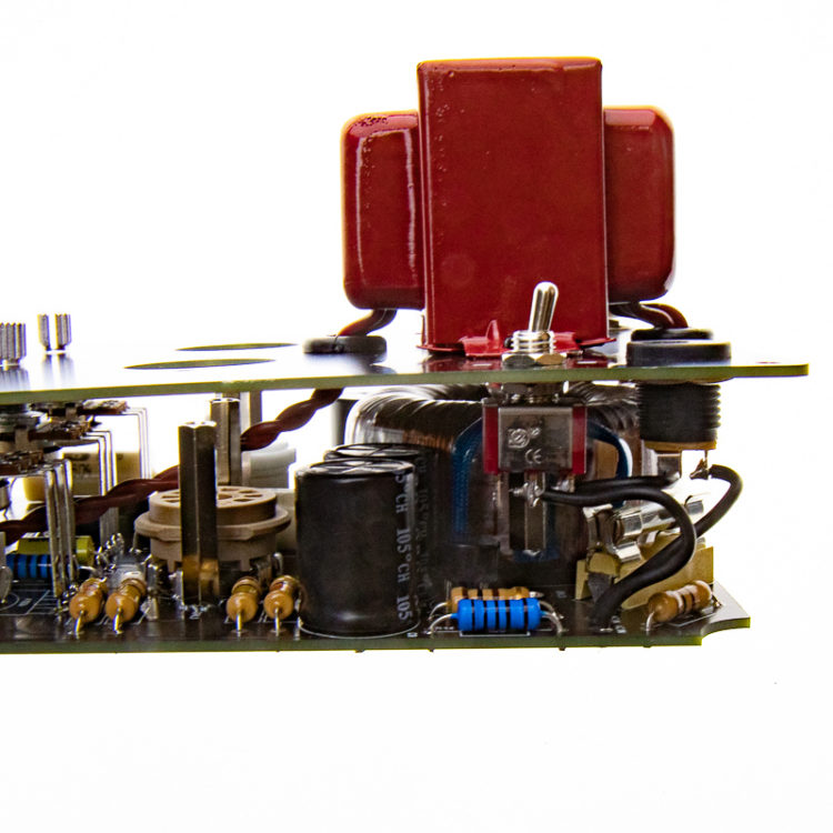
The amplifier should now look like this.

Install the fuse in the socket.

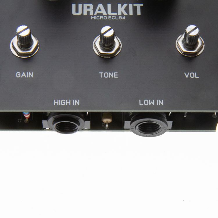
Place all three potentiometers on the PCB (but do not solder yet) and thread two M7 washers on each of their shafts. The height of the parts is adjusted with the washer.
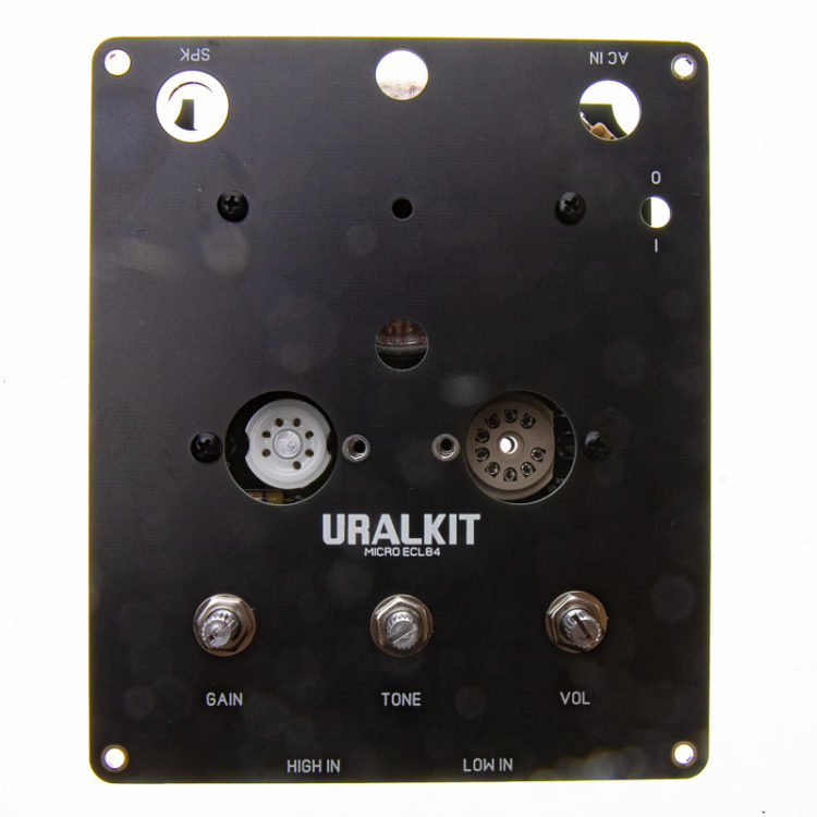
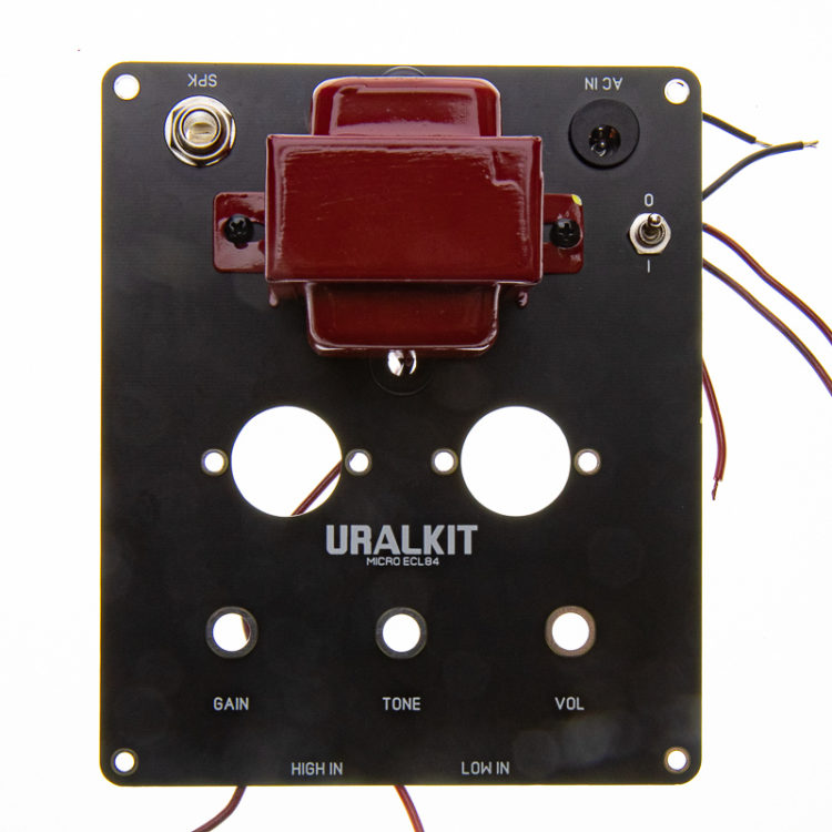
Attach the empty top panel to the PCB with the four screws shown in the picture. With the board attached, screw on the potentiometers. Tighten sufficiently; a loose joint will lift the pads later. The potentiometers rise slightly, but the legs remain on the solder pads.
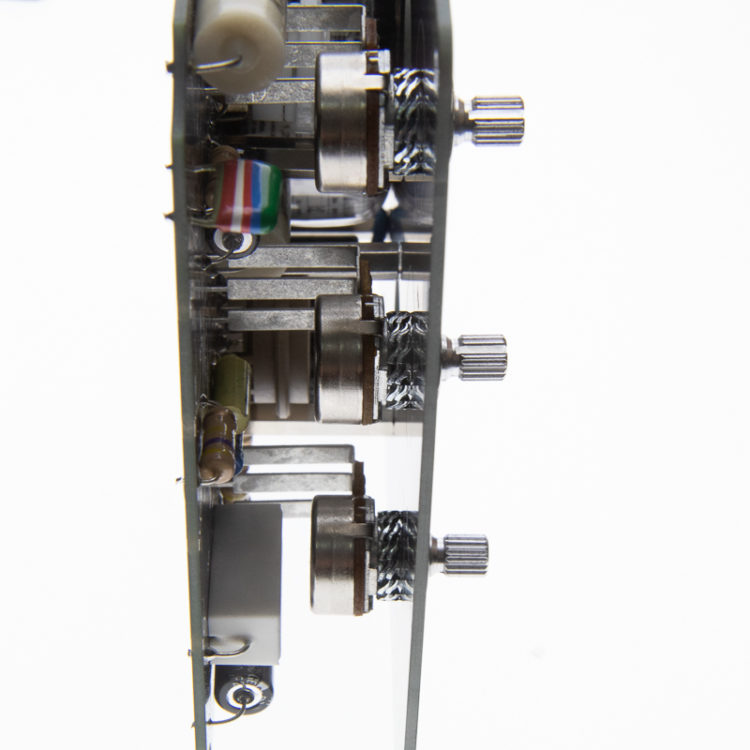
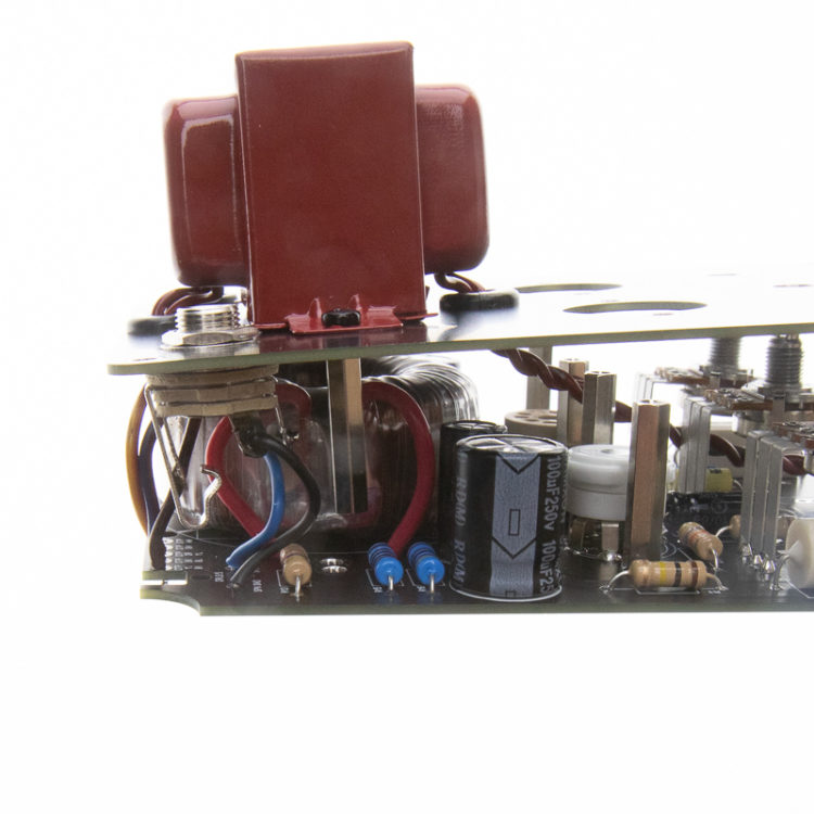
Same from the side. The potentiometer legs are in their solder pads, but the end of the pins partially rises above the plane of the PCB.
Same from the bottom side. The pins of the potentiometer legs are flush with the solder side of the PCB. Solder all three legs of all potentiometers. Do not squeeze the boards together, but solder so that the plates are "at rest".

Remove the potentiometer nuts and cover screws and remove the cover. Solder the legs of the potentiometers from the component side as well. The space is cramped. If the soldering iron tip doesn't fit, your hand shakes, or soldering from the wrong side doesn't seem like a good idea, skip it. The PCB pads are copper-plated, so the tinning of the solder side is already sufficient. Soldering the component side just gives the joint more mechanical resistance.
Remove the two extension bolt risers with star washers next to the transformer.
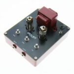
Attach the rubber grommets, DC jack, speaker connector, and finally, the output transformer to the cover plate. Small slices can be cut from the bottom of the through-hole grommets, giving the mains transformer a little more space (cf. the following picture). Attach the output transformer with the distance bolts removed in the previous section (these will be moved to the side of the cover). Don't forget to add the star washers as well. The mounting direction of the transformer is such that the side with the two wires goes towards the tubes and the one with three towards the back.

Solder the wires to the connectors. Note there is a wire that is soldered between the DC jack and the power switch. The wires can be quite short; four centimeters is enough. Twist the primary wires of the transformer as shown. The braided wire is better protected against interference.
Place the cover panel and PCB opposite each other. Do not attach the halves yet. If the loose panels are too tricky to handle, temporarily secure the halves with rubber bands.
Solder the wires of the speaker jack to the board. The pad marked SPK GND goes to the shield of the jack, and the pad marked SPK TIP goes to the tip of the jack.
Solder the power supply wires to the AC IN pads on the board. Polarity doesn't matter; AC voltage has no polarity.

Solder the secondary wires (3 pcs) of the output transformer. The wires of the red transformer are marked on the lower row. BK=black, BL=blue, YL=yellow.
(The upper markings correspond to the coloring of the Hammond 125 series transformer.)
Solder the twisted primary wires of the output transformer. Next to the base of the tube socket are pads OPT RD = red OPT GN = green. Shorten the wire a few centimeters. The correct length is suitably short: there must be room for the cable for installation, as well as room for play if the amplifier needs to be opened. A wire that is too long takes up space inside and can hit the tubes, etc. You can attach these wires to the riser bolt, as shown in the picture. Pass the wire between the tubes.
Fix the halves with screws and install Potentiometer nuts and washers.

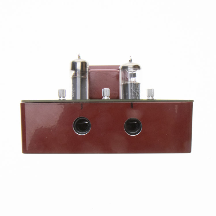
Finally install the input jacks. There are two pairs of pads on the PCB. In this version, the jacks are soldered to the rear, as the aluminum case narrows towards the bottom. If you have decided to drill the enclosure instead of using the top panel PCB then the outer pads might work better.
You can temporarily fix the nuts and pipes of the input jacks in place and test the amplifier. There are high voltages flowing across the board, so make sure that the connection is on an insulating surface (wooden table, etc.) and that there are no legs of the components, etc., under the PCB, which could cause a short circuit.
To install the input jacks two holes must be drilled into the aluminium enclosure. The easiest way to do this is to use a stepped drill bit.
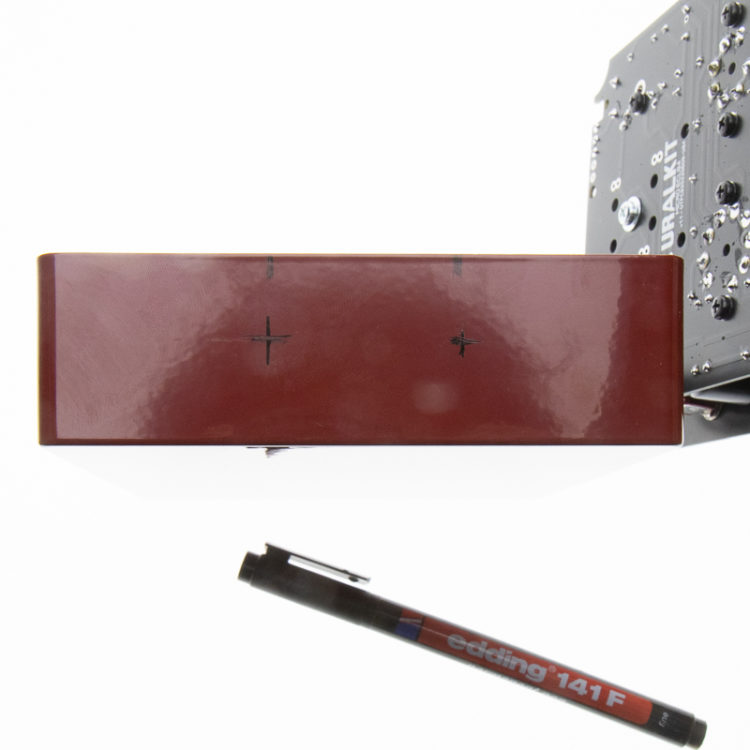
Put the PCB into the enclosure and mark the center point of the jacks with a marker on the box.

Measure the distance between the middle of the jack and the top panel.
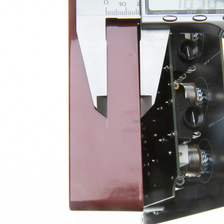
Mark the measured distance to the housing
Continue the vertical lines so that you get the exact drilling locations. There is no undo function when drilling the case, so make a second measurement just in case. Also, don't use the measurements in the pictures. The connection plate may be placed at a different height if the toroidal mains transformer is higher or the heights of the washers vary.
Drill the holes. The diameter of the hole is 12 mm, so the tolerance for drilling is a millimeter. A large drill bit is easier to work with than a small one. The surest way is to tap/mark the beginning with a sharp tool, so the tip doesn't wander. Painted enclosures make the work easier because the paint gives the bit depth. A stepped drill, or progressing with a few drill bits of different sizes, is also a convenient way to control the location of the holes. If the 6mm hole seems to be crooked, this can be "moved" with a round line in the desired direction, after which the hole is drilled larger. With a stepped drill, these moves can be made every 2 mm.
Remove the amplifier from the case and add the plastic washers to the jacks. There are two types of washers, beveled and flat. The flats are used for the inside.

If the output transformer grommets prevent the installation from being centered, cut off a small piece from its edge. Be careful not to break the wires.
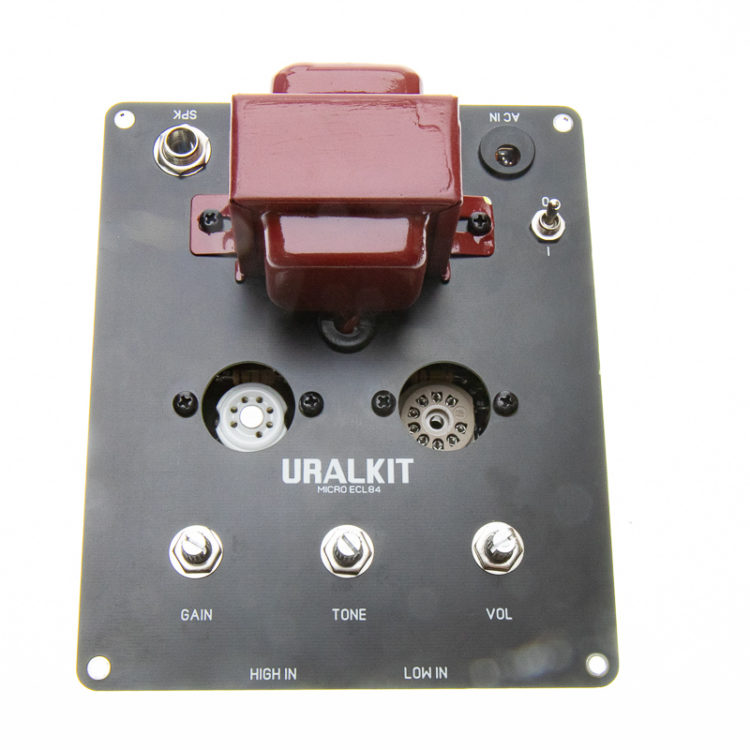
Drop the amplifier into its case. First, fasten the cover screws (the ones in the picture are incorrect and included in the kit are black screws to attach the amplifier to the enclosure) and only after attach the jacks on the front plate. You shouldn't tighten the jacks too tightly, just so they stay on and don't come off. Clean any marker marks from the front plate. Finally, attach the desired potentiometer knobs.
Congratulations, the amplifier is ready!
The amplifiers of the Micro series are all cathode-biased and the amplifier does not need to be adjusted or measured any more. A carefully made amplifier is immediately ready to play.